

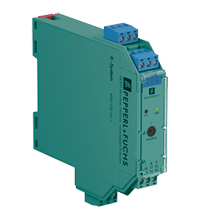
Universal Temperature Converter KFD2-UT2-Ex1-1
- 1-channel isolated barrier
- 24 V DC supply (Power Rail)
- Thermocouple, RTD, potentiometer or voltage input
- Voltage output 0/1 V ... 5 V
- Configurable by PACTware
- Line fault (LFD) and sensor burnout detection
- Up to SIL 2 acc. to IEC/EN 61508 / IEC/EN 61511


Please note: All product-related documents, such as certificates, declarations of conformity, etc., which were issued prior to the conversion under the name Pepperl+Fuchs GmbH or Pepperl+Fuchs AG, also apply to Pepperl+Fuchs SE.
Dane techniczne KFD2-UT2-Ex1-1
| General specifications | ||
|---|---|---|
| Signal type | Analog input | |
| Functional safety related parameters | ||
| Safety Integrity Level (SIL) | SIL 2 | |
| Supply | ||
| Connection | terminals 14+, 15- or power feed module/Power Rail | |
| Rated voltage | 20 ... 30 V DC | |
| Ripple | within the supply tolerance | |
| Power dissipation | ≤ 0.64 W | |
| Power consumption | max. 0.64 W | |
| Interface | ||
| Programming interface | programming socket | |
| Input | ||
| Connection side | field side | |
| Connection | terminals 1, 2, 3, 4 | |
| RTD | type Pt10, Pt50, Pt100, Pt500, Pt1000 (EN 60751: 1995) type Pt10GOST, Pt50GOST, Pt100GOST, Pt500GOST, Pt1000GOST (6651-94) type Cu10, Cu50, Cu100 (P50353-92) type Ni100 (DIN 43760) |
|
| Measuring current | approx. 200 µA with RTD | |
| Types of measuring | 2-, 3-, 4-wire connection | |
| Lead resistance | max. 50 Ω per line | |
| Measurement loop monitoring | sensor breakage, sensor short-circuit | |
| Thermocouples | type B, E, J, K, N, R, S, T (IEC 584-1: 1995) type L (DIN 43710: 1985) type TXK, TXKH, TXA (P8.585-2001) |
|
| Cold junction compensation | external and internal | |
| Measurement loop monitoring | sensor breakage | |
| Potentiometer | 0 ... 20 kΩ (2-wire connection), 0.8 ... 20 kΩ (3-wire connection) | |
| Voltage | selectable within the range -100 ... 100 mV | |
| Input resistance | ≥ 1 MΩ (-100 ... 100 mV) | |
| Output | ||
| Connection side | control side | |
| Voltage output | 0 ... 5 V or 1 ... 5 V ; output resistance: ≤ 5 Ω ; load: ≥ 10 kΩ | |
| Connection | terminals 7-, 8+ | |
| Fault signal | downscale 0 V or 0.5 V, upscale 5.375 V | |
| Fault indication output | ||
| Output type | ||
| Transfer characteristics | ||
| Deviation | ||
| After calibration | Pt100: ± (0.06 % of measurement value in K + 0.1 K (4-wire connection)) thermocouple: ± (0.05 % of measurement value in °C + 1 K (1.2 K for types R and S)) , includes ± 0.8 K fault of the cold junction compensation (CJC) mV: ± 50 µV potentiometer: ± 0.05 % of full scale, (excludes faults due to lead resistance) output: 1 to 5 V output: ± 4 mV from 0 to 103.1 % of span; 0 to 5 V output: ± 4 mV from 0.3 to 102.5 % of span |
|
| Influence of ambient temperature | Pt100: ± (0.0015 % of measurement value in K + 0.0075 % of span)/K ΔTamb*) thermocouple: ± (0.02 K + 0.005 % of measurement value in °C + 0.0075 % of span)/K ΔTamb*) , influence of cold junction compensation (CJC) included: mV: ± (0.01 % of measurement value + 0.0075 % of span)/K ΔTamb*) potentiometer: ± 0.0075 % of span/K ΔTamb*) *) ΔTamb = ambient temperature change referenced to 23 °C (296 K) |
|
| Influence of supply voltage | < 0.01 % of span | |
| Reaction time | worst case value (sensor breakage and/or sensor short circuit detection enabled) mV: 1 s, thermocouples with CJC: 1.1 s, thermocouples with fixed reference temperature: 1.1 s, 3- or 4-wire RTD: 920 ms, 2-wire RTD: 800 ms, Potentiometer: 2.05 s |
|
| Galvanic isolation | ||
| Output/supply, programming input | functional insulation, rated insulation voltage 50 V AC There is no electrical isolation between the programming input and the supply. The programming cable provides galvanic isolation so that ground loops are avoided. |
|
| Indicators/settings | ||
| Display elements | LEDs | |
| Configuration | via PACTware | |
| Labeling | space for labeling at the front | |
| Directive conformity | ||
| Electromagnetic compatibility | ||
| Directive 2014/30/EU | EN 61326-1:2013 (industrial locations) | |
| Conformity | ||
| Electromagnetic compatibility | NE 21:2006 | |
| Degree of protection | IEC 60529:2001 | |
| Protection against electrical shock | UL 61010-1:2004 | |
| Ambient conditions | ||
| Ambient temperature | -20 ... 60 °C (-4 ... 140 °F) | |
| Mechanical specifications | ||
| Degree of protection | IP20 | |
| Connection | screw terminals | |
| Mass | approx. 130 g | |
| Dimensions | 20 x 119 x 115 mm (0.8 x 4.7 x 4.5 inch) (W x H x D) , housing type B2 | |
| Height | 119 mm | |
| Width | 20 mm | |
| Depth | 115 mm | |
| Mounting | on 35 mm DIN mounting rail acc. to EN 60715:2001 | |
| Data for application in connection with hazardous areas | ||
| EU-type examination certificate | CESI 04 ATEX 143 | |
| Marking |  II (1)G [Ex ia Ga] IIC II (1)D [Ex ia Da] IIIC I (M1) [Ex ia Ma] I II (1)G [Ex ia Ga] IIC II (1)D [Ex ia Da] IIIC I (M1) [Ex ia Ma] I |
|
| Input | Ex ia | |
| Inputs | terminals 1, 2, 3, 4 | |
| Voltage | 9 V | |
| Current | 22 mA | |
| Power | 50 mW | |
| Analog outputs, power supply, collective error | ||
| Maximum safe voltage | 250 V (Attention! This is not the rated voltage.) | |
| Interface | ||
| Maximum safe voltage | 250 V (Attention! The rated voltage is lower.), RS 232 | |
| Certificate | TÜV 02 ATEX 1797 X | |
| Marking | II 3G Ex nA II T4 |
|
| Galvanic isolation | ||
| Input/Other circuits | safe electrical isolation acc. to IEC/EN 60079-11, voltage peak value 375 V | |
| Directive conformity | ||
| Directive 2014/34/EU | EN 60079-0:2012+A11:2013 , EN 60079-11:2012 , EN 60079-15:2010 , EN 50303:2000 | |
| International approvals | ||
| UL approval | ||
| Control drawing | 116-0410 | |
| CSA approval | ||
| Control drawing | 116-0314 (cCSAus) 116-0347 |
|
| IECEx approval | ||
| IECEx certificate | IECEx TUN 07.0003 IECEx CML 16.0126X |
|
| IECEx marking | [Ex ia Ga] IIC , [Ex ia Da] IIIC , [Ex ia Ma] I Ex nA IIC T4 Gc |
|
| General information | ||
| Supplementary information | Observe the certificates, declarations of conformity, instruction manuals, and manuals where applicable. For information see www.pepperl-fuchs.com. | |
Classifications
| System | Classcode |
|---|---|
| ECLASS 13.0 | 27210129 |
| ECLASS 12.0 | 27210129 |
| ECLASS 11.0 | 27210129 |
| ECLASS 10.0.1 | 27210129 |
| ECLASS 9.0 | 27210129 |
| ECLASS 8.0 | 27210190 |
| ECLASS 5.1 | 27210107 |
| ETIM 9.0 | EC002919 |
| ETIM 8.0 | EC002919 |
| ETIM 7.0 | EC002919 |
| ETIM 6.0 | EC002919 |
| ETIM 5.0 | EC001485 |
| UNSPSC 12.1 | 32101514 |
Details: KFD2-UT2-Ex1-1
This isolated barrier is used for intrinsic safety applications.
The device converts the signal of a resistance thermometer, thermocouple, or potentiometer to a proportional output voltage.
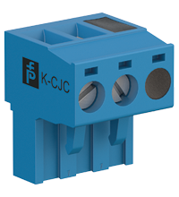
The removable terminal block K-CJC-** is available as an accessory for internal cold junction compensation of thermocouples.
A fault is signalized by LEDs and a separate collective error message output.
The device is easily configured by the use of the PACTware configuration software.
For additional information, refer to the manual and www.pepperl-fuchs.com.
Datasheet: KFD2-UT2-Ex1-1
| Datasheet | Typ pliku | Rozmiar pliku |
|---|---|---|
| Datasheet KFD2-UT2-Ex1-1 | 1184 KB | |
| Fiche de données KFD2-UT2-Ex1-1 | 1190 KB | |
| Datenblatt KFD2-UT2-Ex1-1 | 1185 KB | |
| Datasheet KFD2-UT2-Ex1-1 | 1193 KB | |
| Hoja de datos KFD2-UT2-Ex1-1 | 1189 KB |
Documents: KFD2-UT2-Ex1-1
CAD+CAE: KFD2-UT2-Ex1-1
| CAD | Typ pliku | Rozmiar pliku |
|---|---|---|
| CAD 3-D / CAD 3-D | STP | 2308 KB |
| CAD Portal / CAD Portal | LINK | --- |
| EPLAN | ||
| CAE EPLAN Data Portal / CAE EPLAN Data Portal | LINK | --- |
| CAE EPLAN macro EDZ / CAE EPLAN Makro EDZ | EDZ | 1358 KB |
Approvals+Certificates: KFD2-UT2-Ex1-1
| Certificates | Typ pliku | Rozmiar pliku |
|---|---|---|
| Australia SIMTARS Group I | 326 KB | |
| Brasil TUV Rheinland Brazil | 1204 KB | |
| Canada, USA CSA | 201 KB | |
| China SITIIAS CCC Ex Certificate | 1067 KB | |
| DNV Marine | 114 KB | |
| Europe CESI ATEX Category (1) D ATEX Category (M1) 94/9/EC (ATEX) ATEX Category (1) G | 1531 KB | |
| Europe TUV Nord ATEX Category 3 G | 1285 KB | |
| IECEx nA IECEx Certificate of Conformity | LINK | --- |
| Japan TIIS | 1859 KB | |
| Korea KOSHA | 136 KB | |
| South Africa MASC | 213 KB | |
| TUV Nord IECEx Certificate of Conformity | LINK | --- |
| USA Canada UL Hazardous Location Certificate of Compliance cULus UL E106378 | 410 KB | |
| Ukraine SERTIS Ex | 12351 KB | |
| United Kingdom CML UK-Type Examination Certificate UKEX Category (1) D UKEX Category (1) G UKEX Category (M1) | 146 KB | |
| exida Functional Safety Assessment | 437 KB | |
| Control Drawings | ||
| Control drawing CSA / Control drawing CSA | 67 KB | |
| Control drawing UL / Control drawing UL | 42 KB | |
| Declaration of Conformity | ||
| EU Declaration of Conformity (P+F) / EU-Konformitäterklärung (P+F) | 111 KB |
Software: KFD2-UT2-Ex1-1
| Device type managers (DTM) | Typ pliku | Rozmiar pliku |
|---|---|---|
| DTM Collection Interface Technology 2 / DTM Collection Interface Technology 2 | ZIP | 32633 KB |
| Software Tools | ||
| PACTware 4.1 SP6 / PACTware 4.1 SP6 | ZIP | 43327 KB |
| PACTware 5.0 / PACTware 5.0 | ZIP | 44203 KB |
Produkty powiązane: KFD2-UT2-Ex1-1
| Matching System Components | ||||||
|---|---|---|---|---|---|---|
|
||||||
|
||||||
|
||||||
|
||||||
|
||||||
|
||||||
|
||||||
|
||||||
|
||||||
| Accessories | ||||||
|
||||||
|
||||||
|
||||||
|
||||||


Choose from various selection criteria like safety integrity level, performance level, device function, and signal type and find the SIL/PL assessed device that you are looking for.


Pepperl+Fuchs Sp. z o.o.
ul. Owsiana 12
03-825 Warszawa
Polska
NIP: 522-28-27-777
 +48 22 256 9770
Pepperl+Fuchs jest czołową firmą konstruującą i produkującą czujniki elektroniczne oraz inne komponenty dla globalnego rynku automatyki. Innowacyjność, wysoka jakość oraz stały rozwój firmy powodują, iż z sukcesem jesteśmy obecni na rynku od ponad 70 lat. Pepperl+Fuchs zatrudnia ponad 6300 pracowników na całym świecie i ma swoje zakłady produkcyjne w Niemczech, USA, Singapurze, na Węgrzech, w Indonezji i Wietnamie. Większość z nich posiada certyfikat ISO 9001.